Signal Integrity at High Data Rates
High data rates pose serious challenges to electronics developers. Data signals transmitted via electrical connections are influenced by all kinds of effects that can undermine signal integrity. Because every data connection begins and ends electrically, it is necessary, particularly at high rates, to obviate or compensate for these effects. And that requires specialized knowledge and a comprehensive approach.
Signal integrity in electrical connections
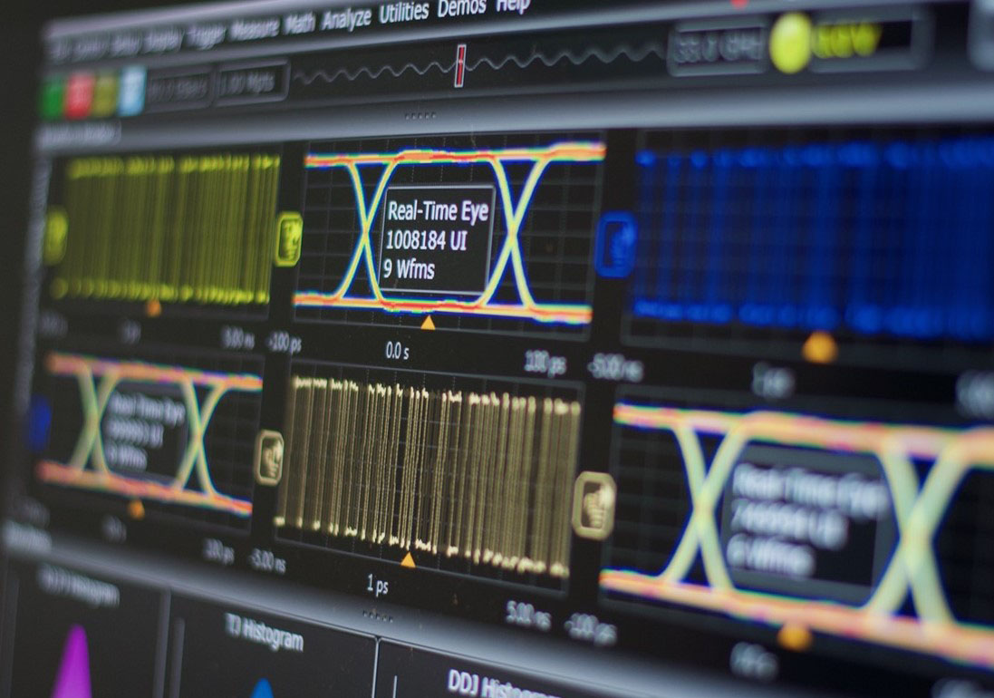
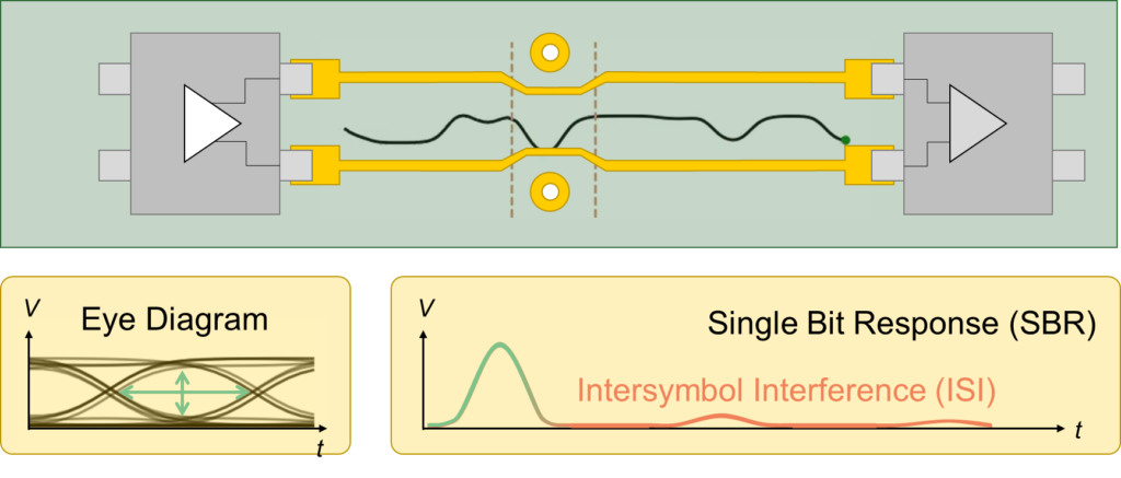
An electrical connection can transmit digital information by converting bits into alternating high and low voltages. If they are to convey the information intact, these ‘electrical bits’ must arrive at the receiver’s end with sufficient quality. Signal integrity is determined by three main effects: reflections, loss and crosstalk, and it can be measured using a so-called ‘eye pattern’.

Reflections
At high data rates, electrical bits tend to behave increasingly like an electromagnetic wave. Changes in trace width, changes of PCB layer (vias) and connectors can cause reflections (or echoes) of the wave. As a result, successive bits may interfere with each other, making it more difficult to distinguish them from each other.
Loss
Information can also disappear from a high-speed electrical data signal because part of the electromagnetic energy is lost in the form of heat. The scale of the loss depends on design choices such as the type of substrate used, the method followed to bond the copper to this, and the use of solder mask. Environmental factors such as temperature, humidity and aging also play a role.

Crosstalk
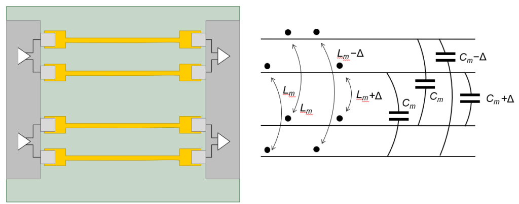
Crosstalk occurs when electrical data connections are placed in close proximity to each other. Inductive and capacitive effects cause electromagnetic interference between the connections, and as a result, signals begin to interfere with each other. This kind of interference, similarly, has a negative effect on signal integrity.
Signal integrity: many factors to control
In total, there are a few dozen parts of your design that may affect the occurrence of reflections, loss and crosstalk. The quality of the power supply (power integrity), cables, the layout of conductors and the optimization of vias are crucial. But so is signal processing: signal modulation, equalizers and error correction. In short: there are many factors that have to be controlled, and to make things worse, these are all interconnected in a complex way.
The so-called Channel Operating Margin (COM) is a standardized metric for signal integrity in high-speed data connections. The COM integrates all factors that affect signal integrity into a single score. This makes it possible to transparently trade off design decisions against each other. The COM also shows the influence that the various parts of a design have on the eye pattern.
Return On Modeling Effort
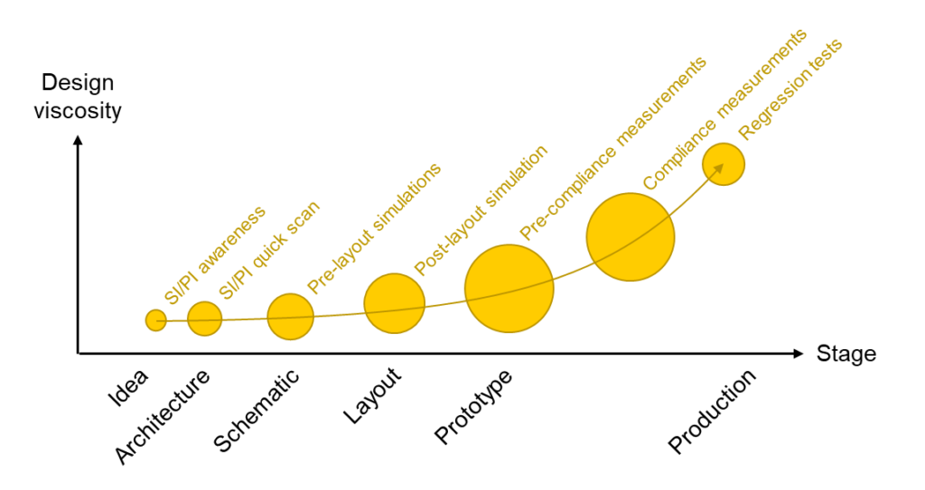
It is important in high-speed development projects that signal integrity is given the attention it deserves, especially in the early phases. This can prevent costly redesigns and delays in later stages. Simulation and measurement are indispensable tools to determine signal integrity. The required investment in time and money is substantial and involves complex tooling, great effort for modeling, verification on the basis of measurement results and optimization of the design. As a result, the Return on Modeling Effort (RoME) may be negative.
TNL has a lot of experience with developing high-speed systems. In addition, we carry out our own research in this field. Our broad expertise in tooling, modeling and optimization means we can realize an optimal RoME for our clients. We offer cost-effective, rapid and valuable insight into the signal integrity of your system.

Our customer cases
Let’s talk about Signal integrity
And find out how we can help you


